
PIC programmers for serial port
Uniprog IV-A1 (Ludipipo)
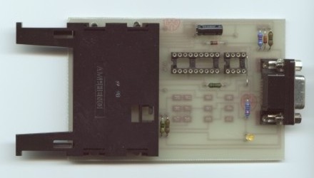
uni4_a1.bmp - PCB of serial programmer UNIPROG IV-A1
uni4_a1o.bmp - layout of components
It is a version of the Ludipipo serial PIC and EEPROM programmer. It don't require a
separate power supply, but takes the power from the serial port of a PC. Connection with
the PC is made by a cable 1-1, 9pin connectors, male-female.
     TxD ---*-----------------------------
     (3)    I                            I
           ---                          ---
           I I                          I I
           I I 2k2                      I I 10k
           ---                          ---
            I       I\I                  I
            *-------I-I-----*---------   I
            I       I/I     I        I   I
          ----\             I +      I   I
           /\  \           ---    14 I   I 4
          /  \    5V6      ---   --------------
          ----         10u  I    I  Vdd Vpp   I
            I               I    I            I
            I               I  5 I            I
     GND ---*---------------*----I Vss        I
     (5)           22k           I            I
                  -----       12 I            I
     RTS ---------I   I----------IRB6 (clock) I
     (7)          -----          I            I
                  -----       13 I            I
     DTR ---------I   I----*-----IRB7 (data)  I
     (4)          -----    I     I            I
                   2k2     I     I  PIC 16C84 I
     CTS ------------------I     I------------I
     (8)
List of components:
-------------------
1 x slot for ISO card
1 x female 9pin connector RS232
1 x resistor 1K0
2 x resistor 2K2
1 x resistor 10K
2 x resistor 22K
1 x capacitor 10-100uF/10-16V
1 x 1N4148
1 x Zener diode 5.6V
1 x LED green
2 x single switch on-on
1 x double switch on-on
1 x socket 8pin
1 x socket 18pin
Uniprog IV-A1 - version "SATHACK.cz"
Setting of switches:
Programming in a socket:
| Type | Chips | SW1 PR1 |
SW2 PR2 |
SW3 PR3 |
| A. az F. | PIC EPROM |
A A |
A A |
A A |
Programming on the board:
Before programming erase (both) PIC (twice in some cases).
| Type | Chips | SW1 PR1 |
SW2 PR2 |
SW3 PR3 |
| A. 1xPIC (RB7) - single PIC card | SLAVE(RB7) | A | A | A |
| B. 1xPIC (RB6) - single PIC card | MASTER(RB6) | A | A | B |
| C. 1xPIC (RB7), 1xEEPROM - Multimac II | EEPROM SLAVE(RB7) |
B A |
B A |
B A |
| D. 2xPIC (RB6, RB7) - twine PIC card | MASTER(RB6) SLAVE(RB7) |
A A |
A A |
B A |
| E. 2xPIC (RB6, RB7), 1xEEPROM - quadra | EEPROM1 MASTER(RB6) SLAVE(RB7) |
B A A |
B A A |
B B A |
| F. 2xPIC (RB6, RB7), 2xEEPROM - quadra Attention! EEPROM2 can be programmed only in a socket! |
EEPROM1 MASTER(RB6) SLAVE(RB7) EEPROM2 |
B A A - |
B A A - |
B B A - |
| G. 1xPIC(RB7) - wafer card | PIC | A | A | A |
| H.1xPIC(RB7), 1xEEPROM - MM2 wafer card | EEPROM PIC |
B A |
B A |
B A |
| J. 1xPIC(RB7), 1xEEPROM - gold MM2 wafer card use Phoenix interface for EEPROM |
PIC EEPROM |
A - |
A - |
A - |
Programming other cards (I have not tested)
Set switch 1 in position A
Use switch 2 to switch between master/slave chip (RB6 CARDS)
Use switch 3 to switch between RB7/RB6 cards (RB7 in position A)
If you program wafer card (or PIC and EEPROM in a socket) only, you can use shorts insted switches:

Stupidpipo - origin designed by Gotcha67
stupidpipo.bmp - PCB of serial programmer Stupidpipo
stupidpipo_o.bmp - layout of components
It is the simplest version of the Ludipipo serial PIC programmer. It don't require a separate power supply, but takes the power from the serial port of a PC. Connection with the PC is made by a cable 1-1, 9pin connectors, male-female.

List of components:
-------------------
1 x slot for ISO card
1 x female 9pin connector RS232
1 x resistor 1K0
2 x resistor 2K2
1 x resistor 10K
1 x resistor 22K
1 x capacitor 10-100uF/10-16V
1 x 1N4148
1 x Zener diode 5.6V
1 x LED green
Programming piccards with PIC16F84A
The simplest way, how to modify Ludipipo for programming PIC16F84A, is a parallel resistor about 8K2, which is connected to resistor 10K. The value of parallel resistor can be reduced to 4K7, but the serial port can be demaged.
Better modification is to use an external power supply. A circuit, which is used insted of the resistor 10K, is described in the next picture:

p16f84_by_Sumero - schema, PCB and layout of components of the Ludipipo modification for programming PIC16F84A.
te_20_sex.bmp - PCB of serial programmer TE-20 SEX
te_20_sex_s.bmp - schematic diagram
te_20_sex_o.bmp - layout of components
Programmer TE-20 SEX is based on the JDM2. (Origin schematic diagram is in jdm2.bmp.) The programmer is suitable for programing PIC16F84, PIC16F84A a PIC16F876 (wafer cards and piccard2) in socket as well as on the board. EEPROM 24Cxx and processor 12C50x can be programmed in a socket only. (To program EEPROM on the board Phoenix or Smartmouse must be used.)
It don't require a separate power supply, but takes the power from the serial port of a PC. Connection with the PC is made by a cable 1-1, 9pin connectors, male-female. Some pins of sockets must be cut before mounting.

List of components:
-------------------
1 x slot for ISO card (CON1)
1 x female 9pin connector RS232 (CON2)
3 x resistor 1K0 (R4, R5, R6)
1 x resistor 1K5 (R2)
1 x resistor 10K (R1)
1 x resistor 100K (R3)
1 x capacitor 22uF/16V (C1)
1 x capacitor 100uF/16V (C2)
4 x 1N4148 (D1, D2, D3, D4)
2 x BC237, BC547B (Q1, Q2)
1 x BC307, BC557B (Q3)
1 x Zener diode 8V2 (Dz1)
1 x Zener diode 5V1 (Dz2)
1 x LED green (DL1 - bad polarization in the original schematic
diagram, use layout of components)
1 x LED red (DL2 - bad polarization in the original schematic
diagram, use layout of components)
1 x jumper-2 pins (JP1)
1 x socket 8pin
1 x socket 18pin
1 x socket 28pin
Download:
Here is the packet te-20_sex.zip only. The packet is a part of the Packet_b, too.
Content of Packet_
b:
- info_b.htm - this page,
- uni4_a1.bmp - PCB of serial programmer UNIPROG IV-A1,
- uni4_a1o.bmp - layout of components,
- stupidpipo.bmp - PCB of serial programmer Stupidpipo,
- stupidpipo_o.bmp - layout of components.
- p16f84_by_Sumero - schema, PCB and layout of components of the Ludipipo modification for programming PIC16F84A,
- te-20_sex.bmp - PCB of serial programmer TE-20 SEX
- te-20_sex_s.bmp - schematic diagram of TE-20 SEX
- te-20_sex_o.bmp - layout of components of TE-20 SEX
- jdm.bmp - origin schematic diagram